The building edge is one system, not two packages
A landscape drawing may stop at the façade line while an architectural detail begins at the wall. Water, soil, roots, paving, thresholds, retaining elements, membranes, insulation, structure, and maintenance do not respect that division. They meet in the same narrow zone, often after different consultants, contractors, suppliers, and approval routes have shaped each part independently.
That is why a sound landscape concept and a sound envelope concept can still produce a weak interface. The question is not whether each package is complete in isolation. It is whether the combined detail gives water a continuous route, people a safe route, plants enough room, materials compatible transitions, maintainers practical access, and the project team a clear record of who resolves each dependency.
A durable building edge is not a line between landscape and architecture; it is a continuous route for water, movement, maintenance, evidence, and responsibility.
Trace water from source to safe destination
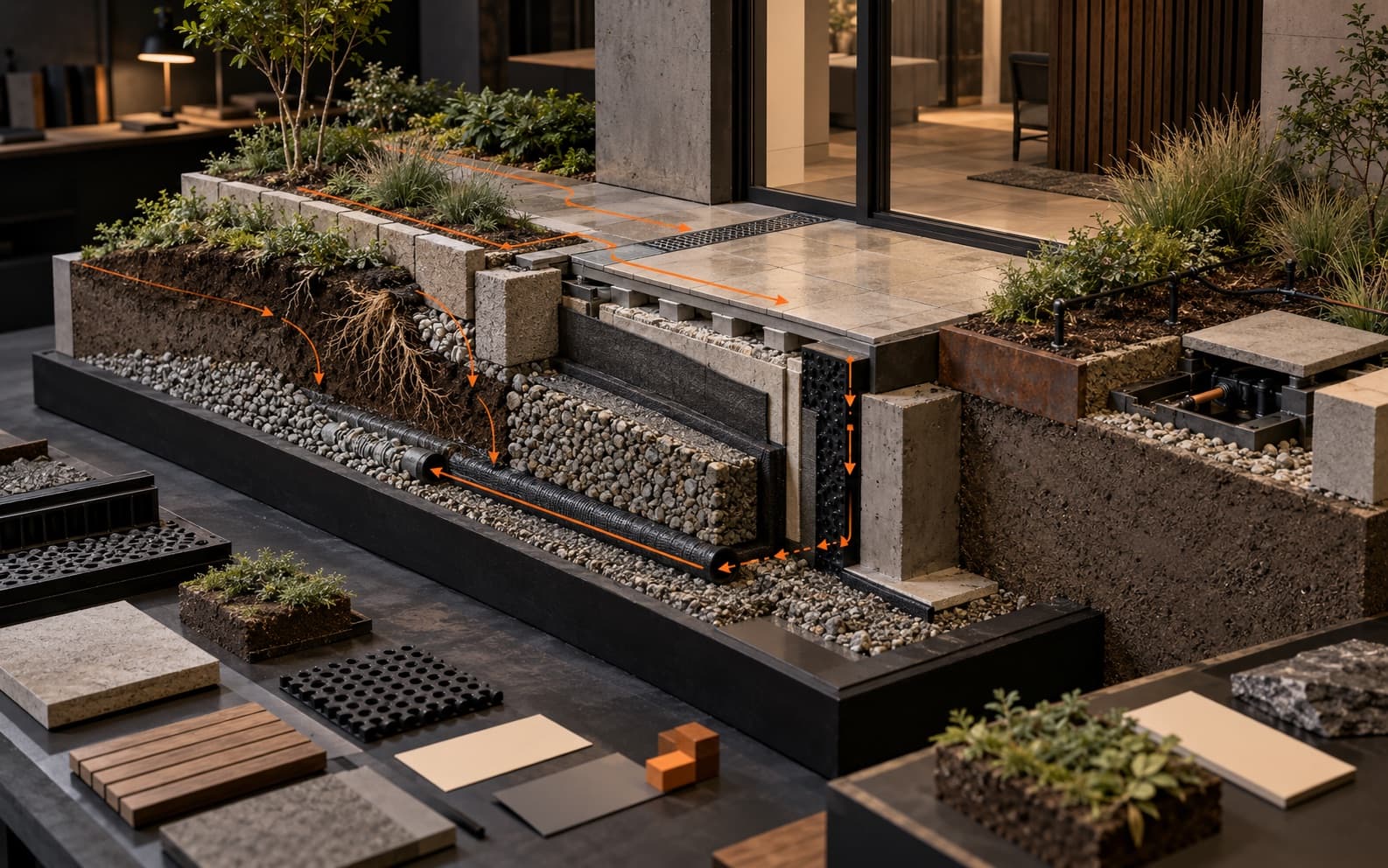
Begin with rainfall, irrigation, overflow, cleaning water, and runoff from higher ground. Draw where each source lands, ponds, infiltrates, crosses a surface, enters a channel, passes an outlet, or reaches an exceedance route. WBDG moisture guidance recommends draining runoff and downspouts away from foundations and combining below-grade sealing with drainage and capillary control [1]. The principle is broader than any one detail: a membrane is not a substitute for controlling the water that reaches it.
Surface-water planning should therefore inform building layout, roads, open space, topography, and green infrastructure early. England's 2025 national SuDS standards explicitly connect those decisions and require systems to be maintainable, structurally durable, and accessible for inspection and intervention [2]. The standards are jurisdiction-specific, but the coordination lesson travels well: show normal flow, blocked-flow behaviour, overflow, temporary storage, discharge authority, maintenance access, and the consequence of failure before finished levels are fixed.
Coordinate finished levels as performance information
A spot level is not merely survey notation. It decides whether water approaches or leaves a door, whether a linear drain has capacity and an outlet, whether a path remains accessible, whether paving can settle without creating a trip edge, and whether a wall base or waterproofing upstand remains exposed enough to perform. Review the building threshold, external landing, paving build-up, falls, drainage slot, soft-landscape level, door movement, façade zone, and structural tolerance as one section.
The U.S. Access Board requires accessible routes to connect site arrival points with accessible facilities and applies surface, slope, opening, and level-change criteria to those routes [3][4]. Those rules do not govern every project, but they demonstrate why accessibility cannot be checked after drainage and threshold geometry are already committed. The durable detail must reconcile local access requirements with weather protection, drainage, thermal continuity, door operation, cleaning, settlement, and construction tolerances.
Treat planting and irrigation as building loads and risks
Planting introduces mature canopy and root volume, seasonal water demand, irrigation, wet soil, nutrients, organic debris, pruning access, replacement work, and changing shade. Record the expected mature condition rather than coordinating only the nursery size. Identify where roots may meet foundations, services, drains, paving, membranes, retaining edges, or movement joints, and where irrigation spray, leakage, or oversaturation could repeatedly wet vulnerable construction.
NHBC guidance for building near trees links species, soil volume-change potential, existing and proposed vegetation, original and final ground levels, foundations, services, drainage, and planting schedules [5]. Its dimensional provisions are intended for defined UK housing conditions, not universal use. The more general lesson is to coordinate vegetation, ground behaviour, structure, services, and drainage from shared site evidence—and to obtain qualified arboricultural, geotechnical, structural, landscape, and drainage advice where the risk requires it.
Make every concealed layer continuous and inspectable
At planters, podiums, terraces, basement edges, and green roofs, the visible landscape sits above layers that may include waterproofing, protection, root resistance, drainage, filtration, insulation, retention media, structure, and outlets. GSA's green-roof guidance describes these as a connected build-up and emphasises drainage and root protection above the waterproofing membrane [6]. A similar discipline applies at vertical and below-grade interfaces even when the exact system differs.
Draw terminations, laps, changes of plane, penetrations, edge restraints, movement joints, inspection points, and repair zones. Confirm chemical and physical compatibility between sealants, membranes, metals, mortars, treated timber, soil, fertiliser, and irrigation components with the relevant manufacturers and specialists. Most importantly, show how the hidden work will be inspected or tested before it disappears beneath paving, soil, cladding, or overburden.
Maintenance is a spatial requirement
A drain that cannot be opened, a membrane edge buried behind permanent work, a tree pit inaccessible to replacement equipment, or an irrigation valve without a safe approach is not fully designed. Reserve access for people, tools, lifting, waste removal, jetting, rodding, filter replacement, pruning, and inspection. Check that routine landscape work will not damage façade coatings, fire-stopping, vents, drainage outlets, lighting, security devices, or accessible routes.
The U.S. EPA advises that green infrastructure needs planned inspection, maintenance, trained responsibility, and records; it also notes that compaction, clogging, sediment, erosion, damaged components, and unmanaged vegetation can reduce performance [7]. Translate that operational guidance into geometry and ownership: access width, working space, isolation, removable elements, sediment capture, inspection frequency, trigger condition, responsible party, and evidence of completed work.
Use the E2W landscape-building interface matrix
For every critical junction, record ten fields: water source and safe destination; movement route; existing and proposed levels; planting and root condition; access for use and maintenance; material transition; inspection or test evidence; design and construction responsibility; decision stage and latest safe date; and status. Attach the relevant plan, section, specification clause, calculation, sample, product data, survey point, or photograph rather than allowing the matrix to become a second set of vague notes.
Prioritise entrances, accessible routes, façade bases, courtyards, podiums, planters, terraces, retaining edges, service penetrations, below-grade walls, roof landscapes, overflow points, and any location where one party's work conceals another's. Review the matrix with architecture, landscape, civil and drainage, structure, envelope, MEP, accessibility, cost, construction, facilities, and specialist suppliers at the stage when the interface can still move.
Close the interface with evidence, not assumption
Before construction, require coordinated sections at a usable scale, agreed benchmarks and datums, drainage and exceedance logic, interface specifications, responsibility boundaries, access strategy, sequencing, hold points, mock-ups where justified, and acceptance criteria. During construction, protect drainage media and membranes, verify falls and outlet continuity, photograph concealed layers, record substitutions, and test the completed route rather than only its individual products.
The matrix is not a universal technical standard and it does not replace project-specific codes, contracts, manufacturer requirements, or competent professional judgment. It is a control surface for a recurring coordination problem: landscape and building durability must be proven across the whole junction. When the team can trace water, movement, levels, roots, materials, access, evidence, responsibility, and stage in one view, package boundaries become manageable instead of invisible.
References
- Mold and Moisture DynamicsWhole Building Design Guide · Accessed 2026-10-13
- National standards for sustainable drainage systems (SuDS)Department for Environment, Food & Rural Affairs · Accessed 2026-10-13
- Guide to the ADA Accessibility Standards: Chapter 4, Accessible RoutesU.S. Access Board · Accessed 2026-10-13
- Guide to the ADA Accessibility Standards: Chapter 3, Floor and Ground SurfacesU.S. Access Board · Accessed 2026-10-13
- NHBC Standards 2024: Chapter 4.2, Building near treesNational House Building Council · Accessed 2026-10-13
- Living Architecture: Green Roofs for Public BuildingsU.S. General Services Administration · Accessed 2026-10-13
- Green Infrastructure Installation, Operation, and MaintenanceU.S. Environmental Protection Agency · Accessed 2026-10-13
More perspectives from E2W.Join the list